RPCT-24C
Certainly. Based on the uploaded datasheet, here is a professional Work Method Statement (WMS) in English for installation of the REPL RPCT-24C 630A Screened Asymmetrical Compact Connector.
WORK METHOD STATEMENT
Installation of RPCT-24C Screened Asymmetrical Compact Connector
1. Scope of Work
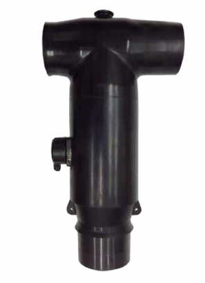
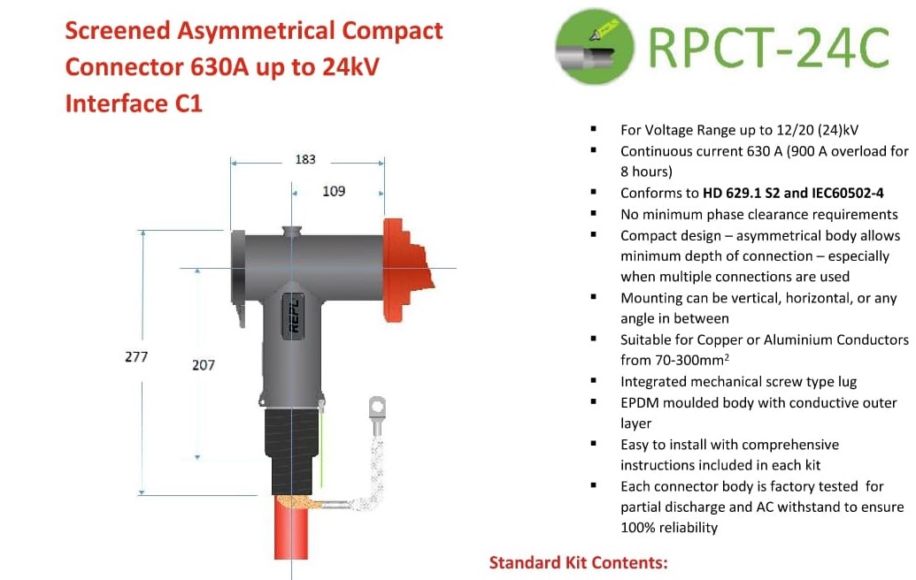
This Work Method Statement describes the procedure for installing the RPCT-24C Screened Asymmetrical Compact Connector, 630A, up to 24 kV, Interface C1, for medium-voltage cable termination.
The work shall be carried out by qualified and authorized electrical personnel in accordance with the manufacturer's installation instructions, approved drawings, and applicable electrical safety requirements.
2. Equipment and Materials
The following materials and equipment shall be prepared:
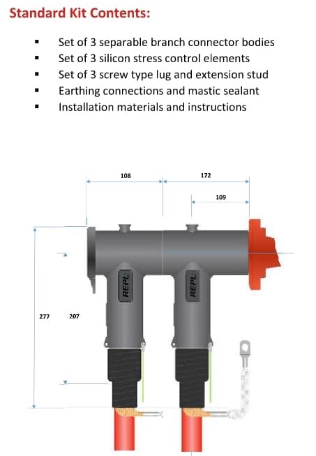
RPCT-24C separable connector set
Appropriate adaptor according to cable insulation diameter
Mechanical screw-type lug suitable for the cable cross-section
Stress control elements
Earthing connection and earth braid
Mastic/sealing materials
Insulating back plug
Cable preparation tools
Cable cutter
Insulation stripping tools
Torque wrench
Hex/socket tools as specified by the manufacturer
Measuring tools
Approved cleaning materials
Personal Protective Equipment (PPE)
3. Technical Data
Item Specification
Product RPCT-24C
Type Screened Asymmetrical Compact Connector
Rated Current 630 A
Voltage Up to 12/20 (24) kV
Interface C1
Conductor Size 70–300 mm²
Cable Insulation Diameter 16.9–39.5 mm
Conductor Material Copper or Aluminium
Standard HD 629.1 S2 / IEC 60502-4
Connector Body EPDM moulded body with conductive outer layer
Lug Type Mechanical screw-type lug
4. Safety Requirements
Before commencing the work:
Confirm that the electrical circuit is isolated, de-energized, and properly locked out/tagged out (LOTO).
Verify absence of voltage using an approved voltage detector.
Apply the required earthing and short-circuiting arrangements.
Barricade the work area and install appropriate warning signs.
Only trained and authorized personnel shall perform the installation.
Wear the required PPE, including:
Safety helmet
Safety shoes
Safety glasses
Electrical gloves as required
Flame-resistant/arc-rated clothing as required by the site risk assessment
Ensure all tools are clean, calibrated where applicable, and suitable for medium-voltage cable installation.
5. Installation Procedure
5.1 Cable Preparation
Confirm the cable type, conductor size, insulation diameter, and termination dimensions against the approved drawings and connector selection table.
Cut the cable to the required installation length.
Remove the cable outer sheath carefully without damaging the metallic screen or insulation.
Prepare the cable screen and earth connection according to the manufacturer's instructions.
Remove the required length of insulation to expose the conductor.
Ensure the insulation surface is clean, smooth, and free from scratches, moisture, dirt, or contamination.
5.2 Connector and Adaptor Selection
Measure the cable insulation diameter.
Select the correct RPCT-24C adaptor code (A–H) based on the measured insulation diameter.
Adaptor Insulation Diameter
A 16.9–19.3 mm
B 18.3–21.0 mm
C 20.0–24.1 mm
D 23.1–27.0 mm
E 25.6–29.0 mm
F 27.7–32.6 mm
G 30.9–36.2 mm
H 34.0–39.5 mm
Select the appropriate mechanical lug according to the conductor cross-section.
Cable Cross Section Mechanical Lug
70–95 mm² RMVL-C 70-95/29
95–150 mm² RMVL-C 95-150/29
150–240 mm² RMVL-C 150-240/29
240–300 mm² RMVL-C 240-300/29
5.3 Mechanical Lug Installation
Insert the prepared conductor into the mechanical lug.
Ensure the conductor is fully inserted and correctly positioned.
Tighten the mechanical screw according to the manufacturer's specified torque and sequence.
Verify that the lug is firmly secured and that there is no movement between the conductor and lug.
Install the connecting stud as specified by the manufacturer.
5.4 Stress Control and Connector Body Installation
Install the stress control components in the correct position.
Apply the approved lubricant, if specified in the manufacturer's installation instructions.
Position the RPCT-24C connector body over the prepared cable.
Ensure the connector is fully seated and correctly aligned.
Install the insulating back plug where applicable.
Ensure the connector body is free from contamination and mechanical damage.
5.5 Earthing and Screen Connection
Connect the cable metallic screen to the earthing braid/earth connection.
Ensure the earth connection is mechanically secure.
Apply the specified mastic and sealing materials.
Check that the conductive outer layer of the connector is properly connected to the cable screen/earth system as required.
6. Inspection and Testing
After installation, perform the following inspections:
Verify correct connector and adaptor selection.
Verify cable conductor size.
Check mechanical lug installation.
Check tightening/torque requirements.
Check connector alignment and seating.
Check cable insulation for damage.
Check stress control components.
Check earthing and screen connections.
Check sealing and mastic application.
Ensure there are no visible gaps, contamination, or mechanical damage.
Perform electrical tests in accordance with the approved testing procedure.
The completed termination shall be inspected and approved by the responsible electrical supervisor before energization.
7. Quality Control
The installation shall comply with:
Approved project drawings and specifications
Manufacturer's installation instructions
HD 629.1 S2
IEC 60502-4
Project quality requirements
Applicable electrical safety regulations
8. Final Acceptance
The RPCT-24C connector shall only be energized after:
Installation has been completed.
All inspection points have been accepted.
Required electrical tests have passed.
Earthing has been verified.
All tools and temporary materials have been removed.
The work area has been cleaned and made safe.
Authorization for energization has been obtained.
9. Important Note
All dimensions, cable preparation lengths, tightening torque values, and installation details shall be verified against the latest manufacturer installation instructions supplied with the RPCT-24C kit. The datasheet shown provides product selection information but does not replace the detailed installation manual.
If by “work” you mean a formal Method Statement / Work Procedure for submission to a client, I can also format this into a professional document with Purpose, Scope, Responsibilities, Tools & Materials, HSE, Step-by-Step Procedure, Inspection & Test Plan (ITP), and Risk Assessment/JSA.
