RIBT REPL - Busbar Insulation Tubes
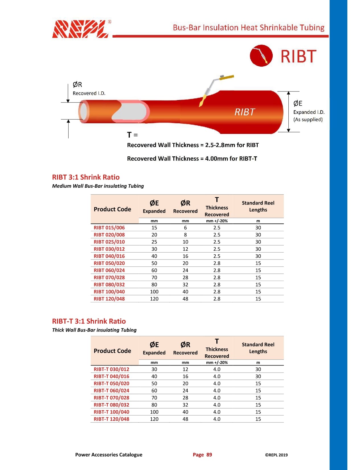
REPL RIBT - Busbar Insulation Tubes
Certainly. Below is a professional English Work Instruction (WI) format based on the RTBM Bus-Bar Insulation Heat Shrinkable Tape information in your image.
WORK INSTRUCTION
APPLICATION OF RTBM HEAT SHRINKABLE BUS-BAR INSULATION TAPE
Document No. WI-EL-RTBM-001
Revision 00
Effective Date __________
Project / Area __________
Department Electrical
Prepared By __________
Checked By __________
Approved By __________
1. PURPOSE
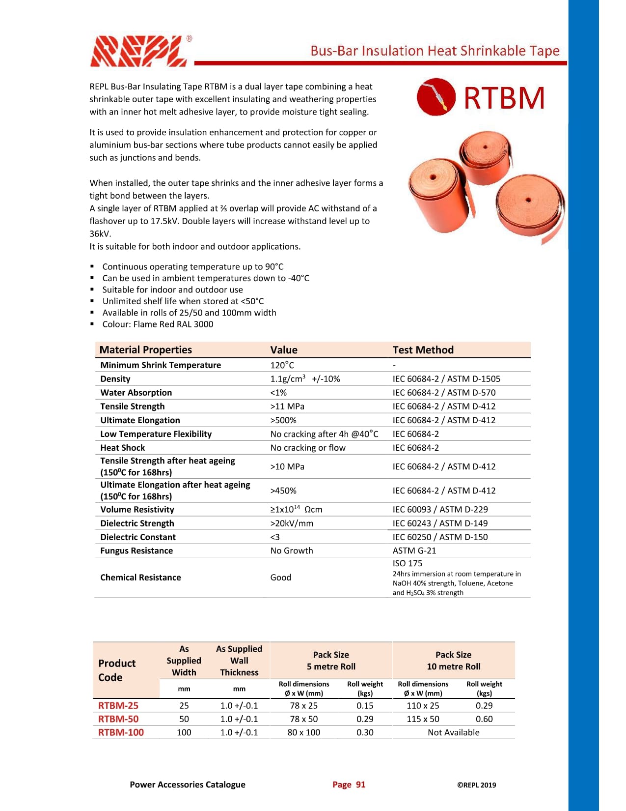
To provide a standard work instruction for the proper application of RTBM Heat Shrinkable Bus-Bar Insulating Tape on rectangular and round bus-bar sections to provide electrical insulation and improve phase-to-phase and phase-to-earth clearance.
2. SCOPE
This work instruction applies to the installation of RTBM insulating tape on:
Rectangular section bus-bars.
Round section bus-bars.
Bus-bar joints and connection areas where insulation is required.
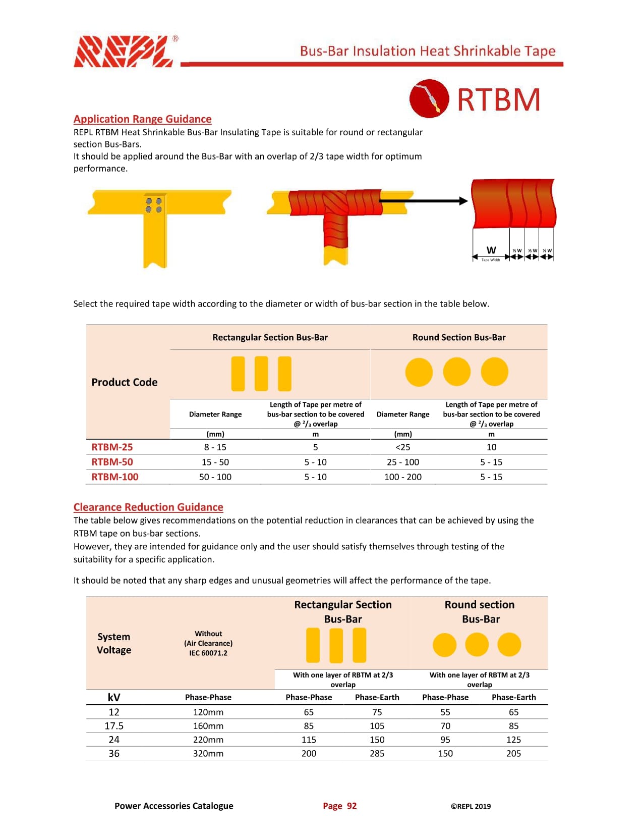
The RTBM tape shall be applied with an overlap of approximately 2/3 of the tape width for optimum performance.
3. REQUIRED MATERIALS AND TOOLS
Materials:
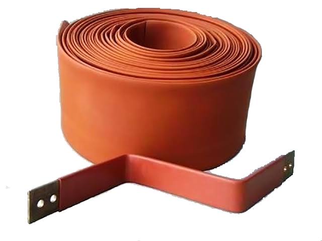
RTBM Heat Shrinkable Bus-Bar Insulating Tape.
Other approved electrical insulation materials, if required.
Tools:
Heat gun / approved heating equipment.
Measuring tape or ruler.
Vernier caliper, if required.
Cutter / insulation knife.
Cleaning cloth.
Temperature measuring device, if required.
PPE:
Safety helmet.
Safety glasses.
Safety gloves.
Safety shoes.
Arc-flash / electrical PPE as required by the site electrical safety procedure.
4. PRE-WORK REQUIREMENTS
Before starting the installation:
Confirm that the bus-bar is isolated, de-energized, and properly grounded in accordance with the applicable electrical safety procedure.
Verify the work area is safe and free from unnecessary materials.
Inspect the bus-bar surface.
Ensure the bus-bar is clean, dry, and free from oil, grease, dust, and other contaminants.
Check the RTBM tape for damage, contamination, or deterioration.
Confirm the required tape size based on the bus-bar width or diameter.
5. RTBM TAPE SELECTION
Product Code Rectangular Bus-Bar Diameter / Width Tape Length per Meter of Bus-Bar Round Bus-Bar Diameter Tape Length per Meter of Bus-Bar
RTBM-25 8–15 mm 5 m < 25 mm 10 m
RTBM-50 15–50 mm 5–10 m 25–100 mm 5–15 m
RTBM-100 50–100 mm 5–10 m 100–200 mm 5–15 m
Note: The required tape length depends on the bus-bar geometry and shall be verified before installation.
6. APPLICATION PROCEDURE
6.1 Preparation
Measure the bus-bar width or diameter.
Select the appropriate RTBM tape according to Section 5.
Clean the bus-bar surface thoroughly.
Ensure there are no sharp contaminants or foreign materials on the surface.
If the bus-bar has sharp edges, take appropriate precautions to prevent damage to the insulation tape.
6.2 Tape Installation
Position the beginning of the RTBM tape on the bus-bar.
Start wrapping the tape around the bus-bar.
Maintain a consistent wrapping tension throughout the installation.
Each turn shall overlap the previous turn by approximately 2/3 of the tape width.
Continue wrapping until the complete required area is covered.
Ensure there are no visible gaps between adjacent layers.
At bus-bar joints or branch connections, ensure the tape follows the bus-bar geometry and provides continuous insulation.
Avoid excessive stretching or deformation of the tape.
6.3 Heat Shrinking
Use an approved heat gun or heating equipment.
Apply heat evenly around the RTBM tape.
Move the heat source continuously to avoid localized overheating.
Allow the tape to shrink and conform closely to the bus-bar surface.
Pay particular attention to joints, corners, and connection areas.
Do not overheat, burn, or damage the tape.
Allow the insulation to cool naturally after heating.
7. OVERLAP REQUIREMENT
The RTBM tape shall be installed with an overlap of approximately:
2/3 × Tape Width
Example:
If the tape width is 30 mm:
Required overlap = 30 × 2/3 = 20 mm
Therefore, approximately 20 mm of each layer shall overlap the previous layer.
8. CLEARANCE GUIDANCE
The following values are guidance for potential clearance reduction when one layer of RTBM tape is applied with a 2/3 overlap.
System Voltage Without Insulation – Phase-Phase Rectangular Bus-Bar Phase-Phase Rectangular Bus-Bar Phase-Earth Round Bus-Bar Phase-Phase Round Bus-Bar Phase-Earth
12 kV 120 mm 65 mm 75 mm 55 mm 65 mm
17.5 kV 160 mm 85 mm 105 mm 70 mm 85 mm
24 kV 220 mm 115 mm 150 mm 95 mm 125 mm
36 kV 320 mm 200 mm 285 mm 150 mm 205 mm
Important: These clearance values are provided as guidance only. The suitability of the RTBM tape for a specific installation shall be verified through the applicable design requirements, standards, and testing.
9. QUALITY CONTROL / INSPECTION CHECKLIST
No. Inspection Item Acceptance Criteria Status
1 Bus-bar surface condition Clean, dry and free from contaminants ☐ OK ☐ NG
2 Tape product Correct RTBM product selected ☐ OK ☐ NG
3 Tape condition No damage, contamination or deterioration ☐ OK ☐ NG
4 Tape overlap Approximately 2/3 of tape width ☐ OK ☐ NG
5 Coverage Complete required area is covered ☐ OK ☐ NG
6 Gaps between layers No visible gaps ☐ OK ☐ NG
7 Heat shrinking Tape properly conforms to bus-bar ☐ OK ☐ NG
8 Overheating No burning or thermal damage ☐ OK ☐ NG
9 Joint / branch area Properly insulated and sealed ☐ OK ☐ NG
10 Final appearance Uniform and free from defects ☐ OK ☐ NG
10. ACCEPTANCE CRITERIA
The installation shall be considered acceptable when:
The correct RTBM tape size has been used.
The bus-bar is completely covered in the required area.
The tape overlap is approximately 2/3 of the tape width.
There are no visible gaps between tape layers.
The tape has properly shrunk and conforms to the bus-bar.
There is no evidence of burning, cracking, tearing, or excessive deformation.
The installation complies with the approved electrical design and applicable project requirements.
11. SAFETY PRECAUTIONS
Do not perform the work on an energized bus-bar.
Follow the applicable Lock Out / Tag Out (LOTO) procedure.
Verify absence of voltage before starting work.
Use appropriate electrical PPE.
Exercise caution when using the heat gun because the working surface and equipment may become hot.
Keep combustible materials away from the heating area.
Do not direct heat continuously at one location.
Follow the manufacturer's recommendations and the project electrical safety requirements.
12. DOCUMENTATION / SIGN-OFF
Description Name Signature Date
Performed By __________ __________ __________
Checked By __________ __________ __________
QA/QC Inspector __________ __________ __________
Approved By __________ __________ __________
Reference: REPL Power Accessories Catalogue – RTBM Bus-Bar Insulation Heat Shrinkable Tape, Page 92.
